
$A$ conducting loop of finite resistance lies on the $x-y$ plane. There is a constant magnetic field in the $z$ direction. The area of the loop varies with time $t$, as $A = A_0 (1 + \sin t)$ in appropriate units. The figure that correctly indicates the qualitative behaviour of the power $P$ dissipated in the loop as a function of time is :
- A
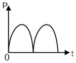
- B
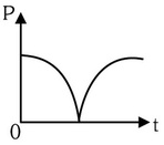
- C
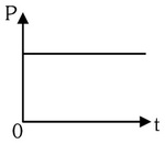
- D
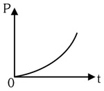
Explore More
Similar Questions
In an $LR$ circuit connected to a battery,the rate at which energy is stored in the inductor is plotted against time during the growth of current in the circuit. Which of the following best represents the resulting curve?
Medium
View Solution$STATEMENT-1$ $A$ vertical iron rod has a coil of wire wound over it at the bottom end. An alternating current flows in the coil. The rod goes through a conducting ring as shown in the figure. The ring can float at a certain height above the coil. Because
$STATEMENT-2$ In the above situation,a current is induced in the ring which interacts with the radial component of the magnetic field to produce an average force in the upward direction.
$STATEMENT-2$ In the above situation,a current is induced in the ring which interacts with the radial component of the magnetic field to produce an average force in the upward direction.
DifficultIIT 2007
View SolutionWhich of the following is constructed on the principle of electromagnetic induction?
Easy
View Solution$A$ circular insulated copper wire loop is twisted to form two loops of area $A$ and $2A$ as shown in the figure. At the point of crossing,the wires remain electrically insulated from each other. The entire loop lies in the plane of the paper. $A$ uniform magnetic field $\vec{B}$ points into the plane of the paper. At $t=0$,the loop starts rotating about the common diameter as an axis with a constant angular velocity $\omega$ in the magnetic field. Which of the following options is/are correct?
[$A$] The rate of change of the flux is maximum when the plane of the loops is perpendicular to the plane of the paper.
[$B$] The net emf induced due to both the loops is proportional to $\cos \omega t$.
[$C$] The emf induced in the loop is proportional to the sum of the areas of the two loops.
[$D$] The amplitude of the maximum net emf induced due to both the loops is equal to the amplitude of maximum emf induced in the smaller loop alone.
[$A$] The rate of change of the flux is maximum when the plane of the loops is perpendicular to the plane of the paper.
[$B$] The net emf induced due to both the loops is proportional to $\cos \omega t$.
[$C$] The emf induced in the loop is proportional to the sum of the areas of the two loops.
[$D$] The amplitude of the maximum net emf induced due to both the loops is equal to the amplitude of maximum emf induced in the smaller loop alone.
$A$ coil of self-inductance $L$ is connected at one end of two rails as shown in the figure. $A$ connector of length $l$ and mass $m$ can slide freely over the two parallel rails. The entire setup is placed in a magnetic field of induction $B$ directed into the page. At an instant $t = 0$,an initial velocity $v_0$ is imparted to the connector,and as a result,it starts moving along the $x$-axis. Which of the following graphs best represents the displacement $x$ of the connector as a function of time $t$?
DifficultAIEEE 2012
View SolutionVedclass Products
For Students
Vedclass Test Series
Mock tests in real JEE/NEET style with performance analysis. 5-day free trial.
Start Free TrialFor Teachers
Exam Paper Generator
Generate Set A/B/C/D exam papers from 7.5L+ questions in 2 minutes. 3 chapters free.
Try FreeFor Institutes
Online Exam Module
Live online exams with unlimited students, 360° analytics & white-label branding.
See Demo