
Class 12PhysicsElectric Potential and CapacitanceCharging and Discharging of Capacitance and RC circuit (DC)
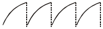
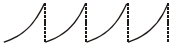
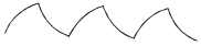
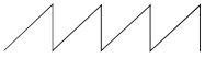
DifficultAn $RC$ circuit as shown in the figure is driven by an $AC$ source generating a square wave. The output wave pattern monitored by $CRO$ would look close to
- A
- B
- C
- D
Explore More
Similar Questions
In the circuit diagram shown,$E = 5 \, V, r = 1 \, \Omega, R_2 = 4 \, \Omega, R_1 = R_3 = 1 \, \Omega$ and $C = 3 \, \mu F$. The magnitude of the charge on each capacitor plate is......$\mu C$.
Medium
View SolutionThe capacitance of $C_1$ and $C_2$ shown in the diagram is $C$. $C_1$ is initially uncharged and $C_2$ is given a charge $2C\varepsilon$ as shown. Which of the following graph represents charge on plate $B$ of capacitor $C_2$ as a function of time?
In the transient current circuit shown,the time constant is
Medium
View SolutionGiven,
${R_1} = 1\,\Omega, R_2 = 2\,\Omega$
${C_1} = 2\,\mu F, C_2 = 4\,\mu F$
The time constants (in $\mu s$) for the circuits $I, II, III$ are respectively:
${R_1} = 1\,\Omega, R_2 = 2\,\Omega$
${C_1} = 2\,\mu F, C_2 = 4\,\mu F$
The time constants (in $\mu s$) for the circuits $I, II, III$ are respectively:
Difficult
View SolutionIn the following circuit,the switch $S$ is closed at $t = 0.$ The charge on the capacitor $C_1$ as a function of time will be given by $\left( {{C_{eq}} = \frac{{{C_1}{C_2}}}{{{C_1} + {C_2}}}} \right).$
DifficultJEE MAIN 2018
View SolutionVedclass Products
For Students
Vedclass Test Series
Mock tests in real JEE/NEET style with performance analysis. 5-day free trial.
Start Free TrialFor Teachers
Exam Paper Generator
Generate Set A/B/C/D exam papers from 7.5L+ questions in 2 minutes. 3 chapters free.
Try FreeFor Institutes
Online Exam Module
Live online exams with unlimited students, 360° analytics & white-label branding.
See Demo