
In the circuit shown,the switch $S_1$ is closed at time $t = 0$ and the switch $S_2$ is kept open. At some later time $t_0$,the switch $S_1$ is opened and $S_2$ is closed. The behavior of the current $I$ as a function of time $t$ is given by:
- A
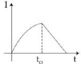
- B
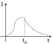
- C
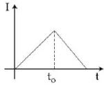
- DNone of these
Explore More
Similar Questions
In the circuit shown in the figure, what is the value of $I_1$ just after pressing the key $K$?
Difficult
View SolutionThe figure shows a circuit containing three resistors ($9 \ \Omega$ each) and two inductors ($4 \ mH$ each). The reading of the ammeter at the moment the switch $K$ is turned $ON$ is $...... \ A$.
In the circuit shown, when the current $i$ is $3 \text{ A}$ and increasing at the rate of $1 \text{ A/s}$, the potential difference between $A$ and $B$ is $12 \text{ V}$. When the same current $3 \text{ A}$ is decreasing at the rate of $1 \text{ A/s}$, the potential difference between $A$ and $B$ is $6 \text{ V}$. The value of $R$ in the circuit is: (in $\text{ } \Omega$)
DifficultMHT CET 2026
View SolutionThe time constant of an $LR$ circuit is $10 \, s$. When a resistance of $10 \, \Omega$ is connected in series with the existing circuit,the time constant becomes $2 \, s$. The self-inductance of the circuit is ..... $H$.
Difficult
View SolutionIn a decaying $L-R$ circuit,the time after which energy stored in the inductor reduces to one-fourth of its initial value is
Difficult
View SolutionVedclass Products
For Students
Vedclass Test Series
Mock tests in real JEE/NEET style with performance analysis. 5-day free trial.
Start Free TrialFor Teachers
Exam Paper Generator
Generate Set A/B/C/D exam papers from 7.5L+ questions in 2 minutes. 3 chapters free.
Try FreeFor Institutes
Online Exam Module
Live online exams with unlimited students, 360° analytics & white-label branding.
See Demo